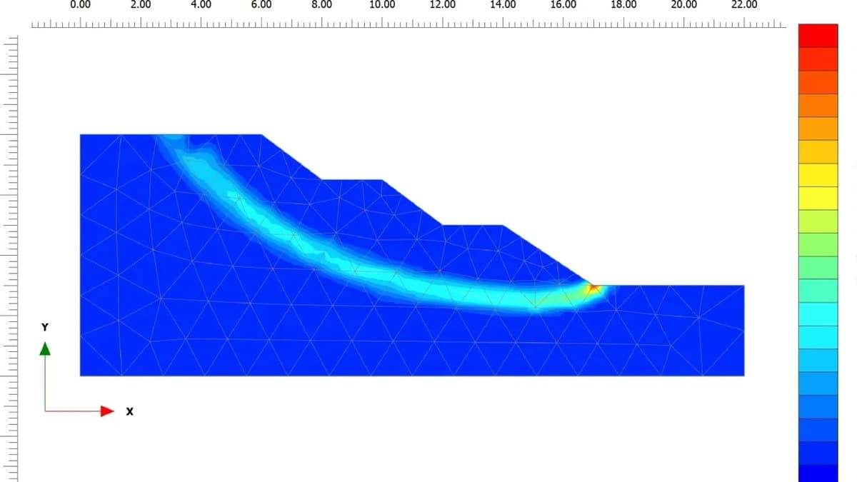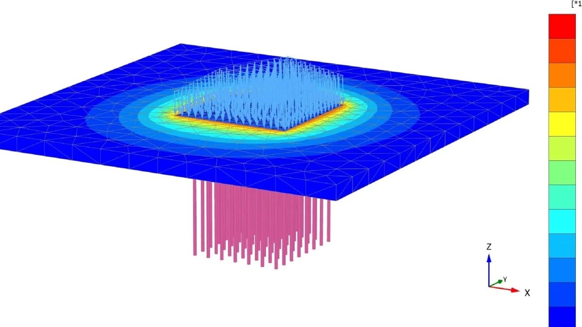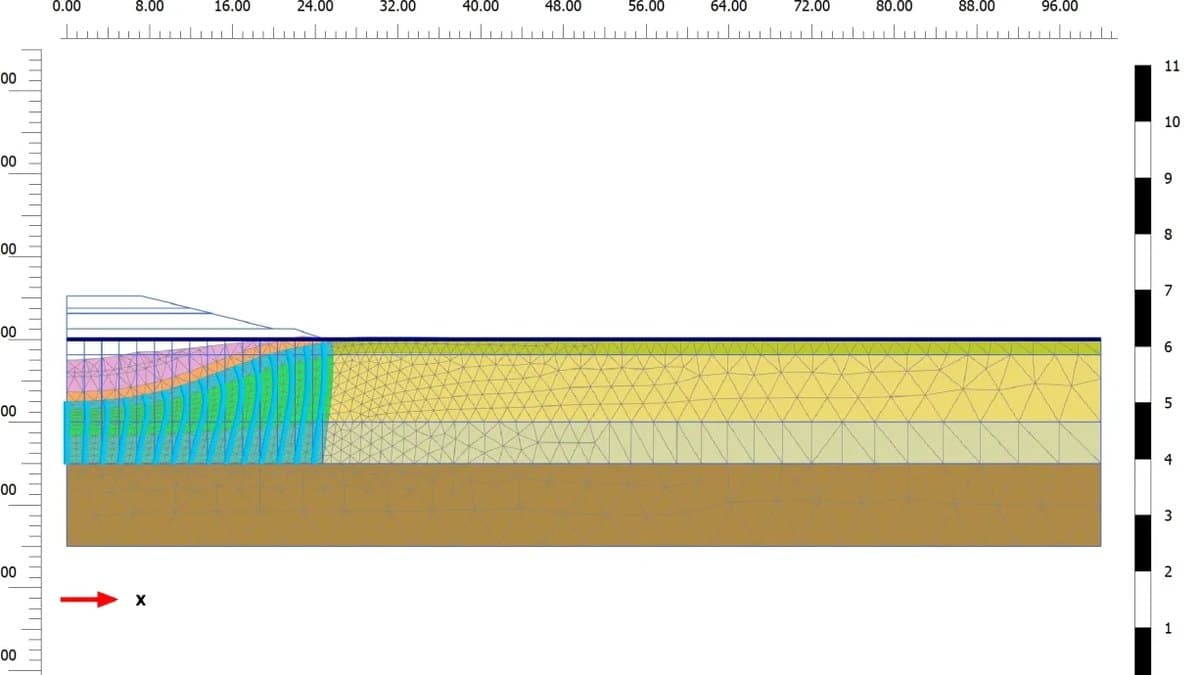





A deep excavation reverses the usual geotechnical problem. Instead of loading the ground, you unload it, and the ground pushes back: the retained soil drives the wall inwards, the base heaves upwards, and every millimetre the wall moves reappears as settlement behind it. In a city, the things least able to tolerate that movement, adjacent buildings, roads and buried services, are exactly what the pit sits beside.
Classical earth-pressure methods will size a wall for stability. They say almost nothing about how much the ground will move, or at which stage of construction. That is why staged finite element analysis has become the standard of care for excavation design, and why PLAXIS 2D is the tool most geotechnical engineers use to run it.
What makes a deep excavation hard
Four mechanisms compete to govern the design:
- Wall deflection. The wall bends between support levels, and its stiffness, embedment and propping sequence set how far it moves. Monitored walls commonly deflect a few tenths of a percent of the excavation depth, and specifications cap it tighter near sensitive structures.
- Ground movement behind the wall. The soil follows the wall. The settlement trough typically reaches two to four times the excavation depth behind it, which in a dense street puts foundations, sewers and tunnels inside the zone of influence.
- Basal heave. In soft clay the base can fail like an inverted bearing-capacity problem, with soil flowing under the wall toe and up into the pit. Long before failure, unloading heave lifts the base and drives further wall movement.
- Groundwater. Digging below the water table turns the pit into a well. Seepage can boil the base in sand, an unrelieved confined aquifer can burst a clay plug by uplift, and dewatering outside the wall consolidates the ground and settles the neighbourhood.
The analysis follows the construction sequence
An excavation is not one load case; it is a history. The wall goes in, the water table is lowered, a lift of soil comes out, a strut or anchor is installed, and the cycle repeats to formation level. Each step starts from the stresses the previous one left behind. Staged construction in PLAXIS 2D mirrors this directly: every phase activates or deactivates soil clusters, structural elements and water conditions, and carries the stress state forward.
The stress path matters as much as the sequence. Excavation is unloading, and soil is far stiffer in unloading and reloading than in first loading, typically by a factor of three or more. A soil model with a single stiffness cannot represent the loaded side of the wall and the unloaded base at the same time:
| Soil model | Stiffness behaviour | Use for excavations |
|---|---|---|
| Mohr-Coulomb | One stiffness for loading and unloading | First estimates; overpredicts base heave |
| Hardening Soil | Separate, higher unloading-reloading stiffness | The practical standard for walls and settlements |
| HS small-strain | Adds high stiffness at very small strains | Most realistic settlement troughs behind the wall |
| Soft Soil / Soft Soil Creep | Compression and creep of soft clay | Deep pits in soft ground, where basal heave governs |
Modelling the wall, struts and anchors
The wall is a plate element carrying axial stiffness EA and bending stiffness EI per metre run, whether it stands for a diaphragm wall, secant piles or sheet piles. Interface elements along both faces let the soil slip and separate against the wall at a reduced friction, rather than sticking to it with the full soil strength.
Supports are modelled as what they are:
- Struts become fixed-end anchors: an axial spring with the real member stiffness, divided by the horizontal spacing to give a per-metre value in plane strain.
- Ground anchors combine a node-to-node anchor for the free length with an embedded grout body for the bond length, prestressed in the phase they are stressed on site.
- Berms left temporarily against the wall are soil clusters removed in a later phase, and the stages they buy are often the difference between a wall that works and one that does not.
Groundwater, dewatering and flow
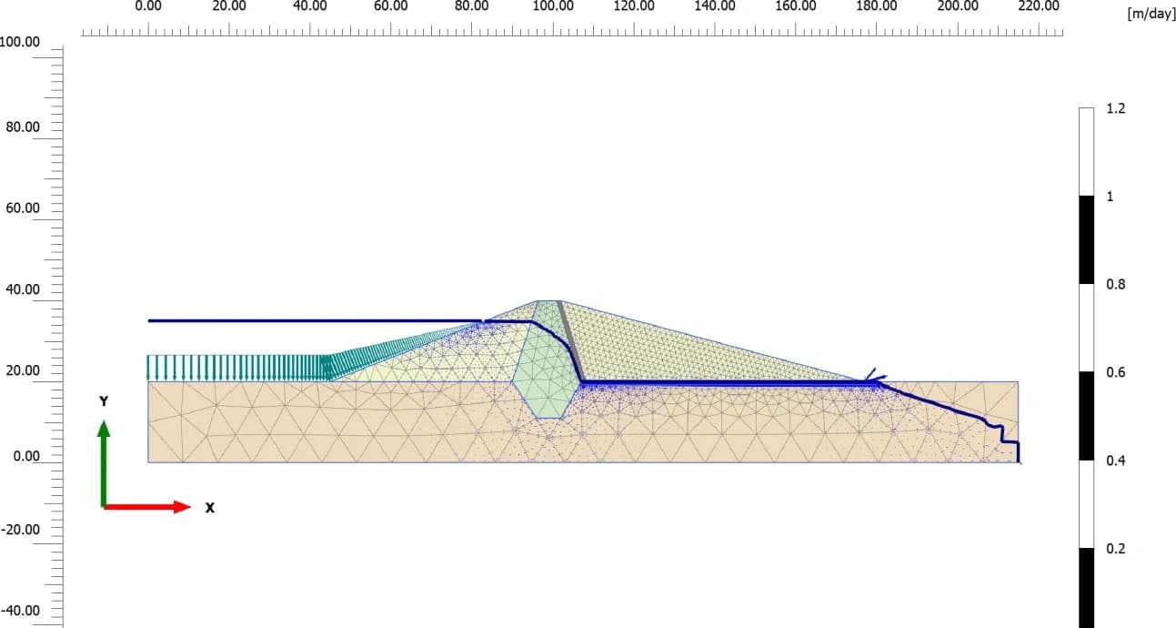
Half the difficulty of a deep excavation is water. PLAXIS 2D computes groundwater flow on the same mesh as the deformation analysis: water levels are lowered inside the wall phase by phase, wells and drains are activated where the scheme uses them, and the resulting flow field returns pore pressures, seepage quantities and hydraulic gradients. In clays, a coupled consolidation analysis adds time: how fast excess pore pressures dissipate, and how much settlement each week of an open pit costs.
The flow results feed the checks that hand methods handle worst: piping at the wall toe in granular soils, uplift of a low-permeability plug over a confined aquifer, and drawdown outside the wall together with the consolidation settlement it causes.
The outputs that govern
The result set that decides the design is short:
- Wall bending moment and shear, taken as an envelope over every stage, size the wall section and its reinforcement.
- Wall deflection, per stage, is checked against the movement limits in the specification.
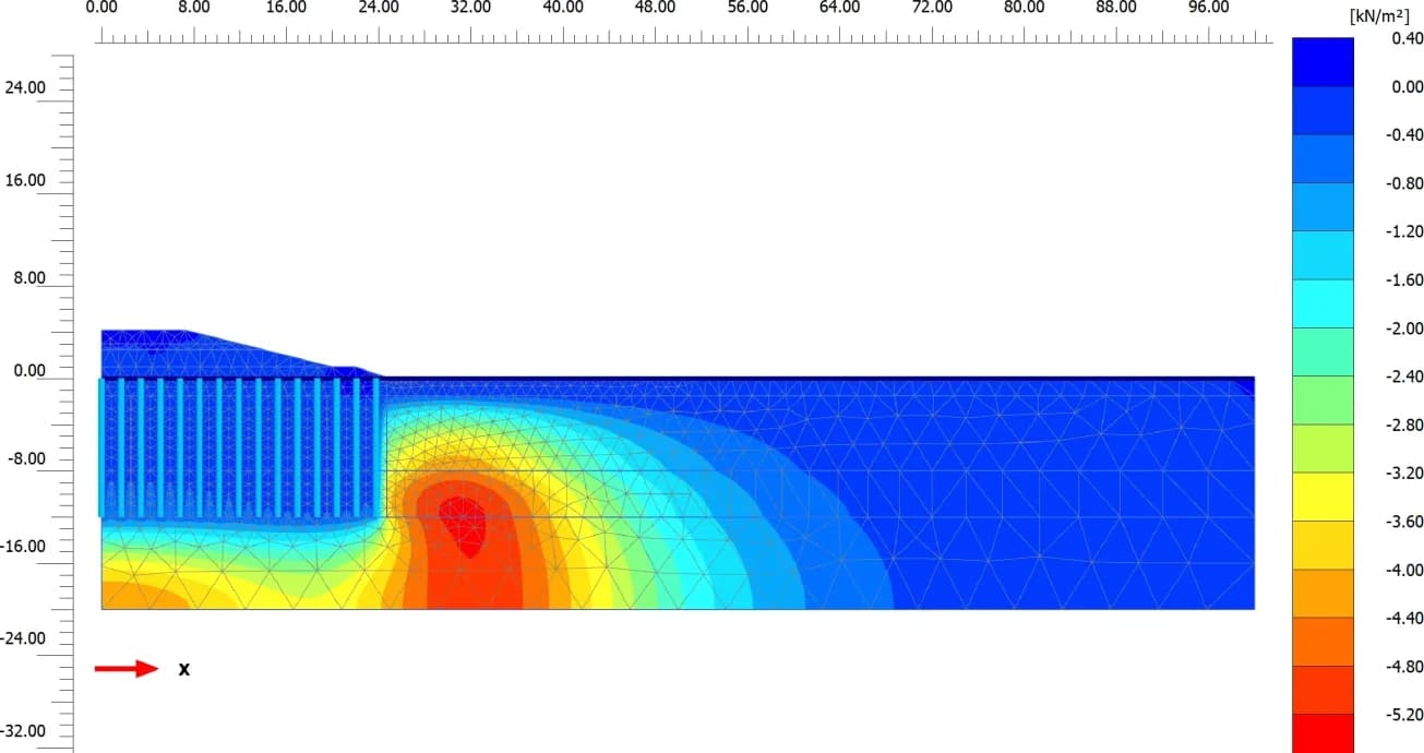
- Ground settlement behind the wall, both the trough shape and its extent, drives the damage assessment for adjacent buildings.
- Strut and anchor forces, per stage, size the support members and their connections.
- Factor of safety by strength reduction, run at the critical stages rather than only at final dig.
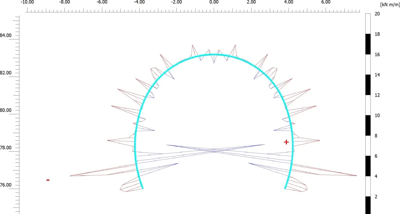
One caution on geometry: plane strain is the right idealisation for long, straight runs of wall, and it errs on the safe side there because corners stiffen a real pit. Short pits, shafts and wall corners are genuinely three-dimensional and belong in a 3D model. For the long sections that dominate most projects, a staged 2D analysis with the right soil model and honest groundwater conditions remains the fastest route to a design that can be defended, and a prediction that site monitoring can be checked against.
The tool for this

Finite-element analysis for soil and rock.
Model deep excavations, slopes, tunnels and foundations in 2D and 3D, with staged construction, consolidation and dynamic analysis.
FAQs
Why is staged construction analysis essential for deep excavations?
Because each construction step starts from the stresses the previous one left behind. Installing a strut before or after a lift of excavation changes every wall moment and movement that follows, and the governing values often occur at an intermediate stage. A single final-geometry analysis cannot reproduce that history.
Which soil model should be used for excavation analysis in PLAXIS 2D?
The Hardening Soil model, or its small-strain variant, is the usual choice because excavation unloads the ground and these models carry a separate, much higher unloading-reloading stiffness. A single-stiffness Mohr-Coulomb model tends to overpredict base heave and distort the settlement trough, so it is kept for first estimates.
How does PLAXIS 2D handle groundwater in an excavation model?
Groundwater flow is computed on the same mesh as the deformation analysis. Each phase can lower the water level inside the pit, activate wells or drains, and recompute the pore pressure field. The results support the water-driven checks: piping at the toe, uplift of the base over a confined aquifer, and settlement from drawdown outside the wall. In clays, coupled consolidation adds the time dimension.
What outputs from the analysis govern the design?
The wall bending moment envelope across all stages sizes the wall. Wall deflection and the settlement trough behind it are checked against movement limits and drive the assessment of adjacent buildings. Strut and anchor forces size the support system, and strength-reduction factors of safety confirm stability at the critical stages.