




Soil has no data sheet. Its stiffness changes with stress level and strain, its strength depends on how fast it is loaded and how well it drains, and it keeps deforming for years after construction ends. The closed-form solutions taught in every foundation course assume none of this: a uniform half-space, a rigid footing, one load applied once.
Real projects rarely oblige. A deep excavation unloads the ground in stages while the water table is drawn down. A tunnel redistributes stress in three dimensions ahead of its own face. An embankment on soft clay gains strength only as fast as the pore water escapes. Finite element analysis is the numerical method that takes these problems as they are, and it has become the working standard for slopes, foundations, retaining structures, excavations and tunnels.
This guide covers what the method does, why geotechnical problems demand it, how constitutive models, meshes and construction stages fit together, and which outputs an engineer should read.

What finite element analysis is
The method divides the ground, and the structures in it, into a mesh of elements connected at nodes. Each element carries a material model, and the assembly is loaded through the applied forces, prescribed displacements and groundwater conditions. The software then solves for the displacement field that puts the whole system in equilibrium. Because soil behaviour is nonlinear, that solution is found by iteration: loads go on in increments and stiffness is updated as elements yield.
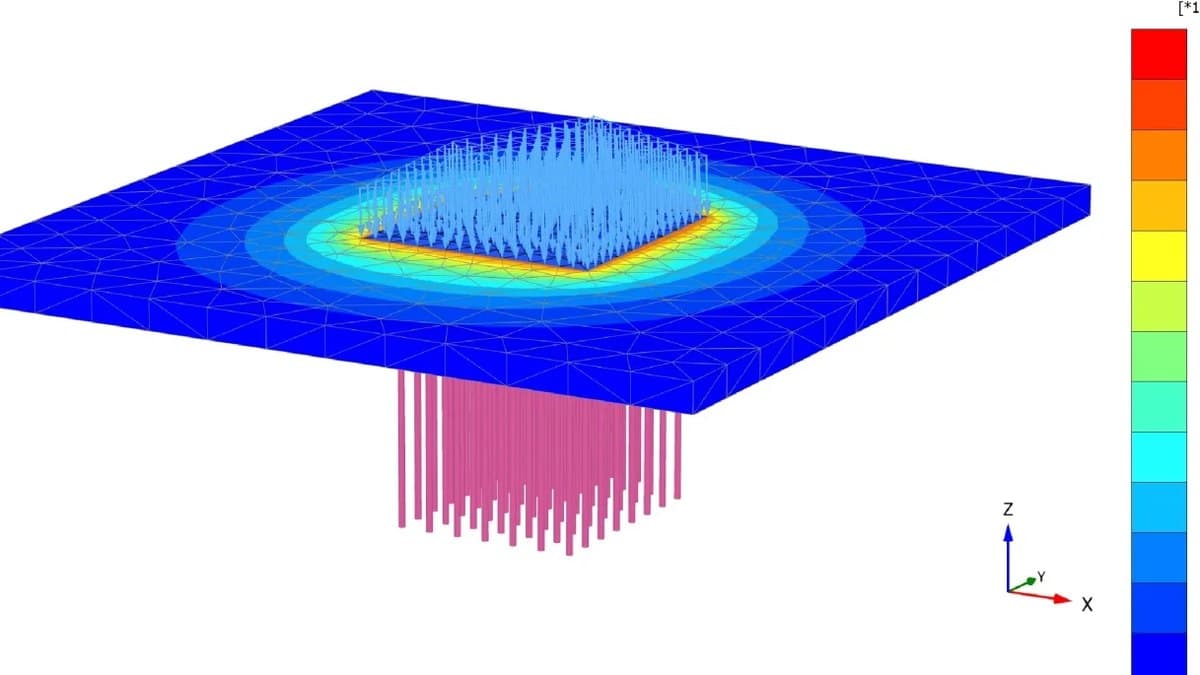
Two-dimensional models cover most daily work. Plane strain suits long, uniform geometry such as retaining walls and embankments; axisymmetry suits single piles and circular tanks. Full 3D models are reserved for problems where the geometry or the loading genuinely varies in all three directions.
Why soil demands it
- Nonlinear from the first increment. No single Young's modulus describes a soil. Stiffness falls as strain grows and rises with confining stress, so the "right" modulus depends on the very answer being sought.
- Stress path matters. Excavation unloads the ground; an embankment loads it. The same soil responds to each with a different stiffness, which is why heave and settlement problems cannot share one parameter set.
- The sequence changes the answer. Wall forces in a propped excavation depend on when each prop went in relative to each dig level. A single-stage calculation has no way to represent that history.
- Water carries part of every load. Strength and deformation are governed by effective stress. Loading a clay generates excess pore pressure that can take months or years to dissipate, and stability is often worst part-way through that process.
- Ground and structure interact. Wall bending moments depend on soil stiffness, and the soil movements depend on wall stiffness. Solving one while assuming the other is fixed misses both.
Chart solutions and hand methods keep their place for preliminary sizing and for order-of-magnitude checks. They stop being trustworthy the moment layering, geometry, staging or groundwater departs from the idealised case they were derived for.
Constitutive models in brief
The constitutive model is the mathematical description of how an element of soil responds to stress. It is the most consequential modelling decision on the job, because everything downstream, from the settlement trough to the factor of safety, inherits its assumptions.
| Model | What it captures | Typical use |
|---|---|---|
| Linear elastic | Constant stiffness, no failure | Structural elements, intact rock, first estimates |
| Mohr-Coulomb | Elastic-perfectly-plastic failure with c and φ | Stability checks, first nonlinear pass |
| Hardening Soil | Stress-dependent stiffness, separate loading and unloading moduli | Excavations, foundations, working-load deformations |
| HS small-strain | Added stiffness at very small strains | Movements remote from the load, dynamic analysis |
| Soft soil creep | Time-dependent compression of clays and peats | Embankments on soft ground, long-term settlement |
Move down the table as the question shifts from stability to deformation, and as the cost of being wrong grows. Advanced models demand more laboratory data; the trade is real, and it is worth making whenever displacements govern the design.
Meshing, boundaries and interfaces
Mesh density belongs where stress gradients are steep: beneath footing edges, around a tunnel, at the toe of a wall. Elsewhere it can coarsen. The only proof a mesh is adequate is a convergence check: refine, re-run, and confirm the displacements of interest have stopped changing.
Model boundaries must sit far enough from the works that they neither attract stress nor block the failure mechanism. Fixities follow convention, with the base fixed and vertical sides restrained horizontally, but the distance is the judgement call, and a boundary placed too close reads as an artificial stiffening of the ground.
Between soil and structure, interface elements allow slip and separation and carry a reduced wall friction. Leaving them out welds the soil to the wall, which distorts both the earth pressure distribution and the structural forces taken from the model.
Staged construction and groundwater coupling
A geotechnical model is built the way the works are built. The analysis starts from the initial stress state in the ground, then activates and deactivates parts of the model stage by stage: excavate a lift, install an anchor and stress it, place fill, lower the water table, let consolidation run. Forces and displacements accumulate through the sequence, which is why a single-stage model of a staged problem gets both wrong.
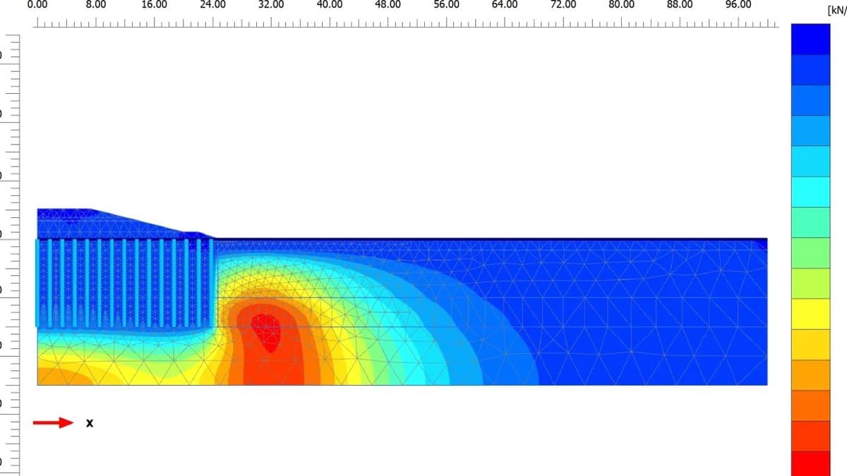
Groundwater is coupled into the same solution. Steady-state seepage sets the pore pressures for drained stages, while consolidation analysis tracks how the excess pore pressures generated by loading dissipate with time, converting into effective stress and settlement as they go. On soft ground this coupling is the analysis: the safe rate of construction is read directly from it.
What the outputs tell you
- Deformed mesh. The first check, viewed at exaggerated scale. If the mechanism looks wrong here, no contour plot downstream deserves trust.
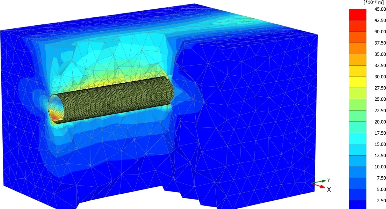
- Displacement contours. Settlement troughs, heave and wall deflections, compared directly against serviceability limits and monitoring triggers.
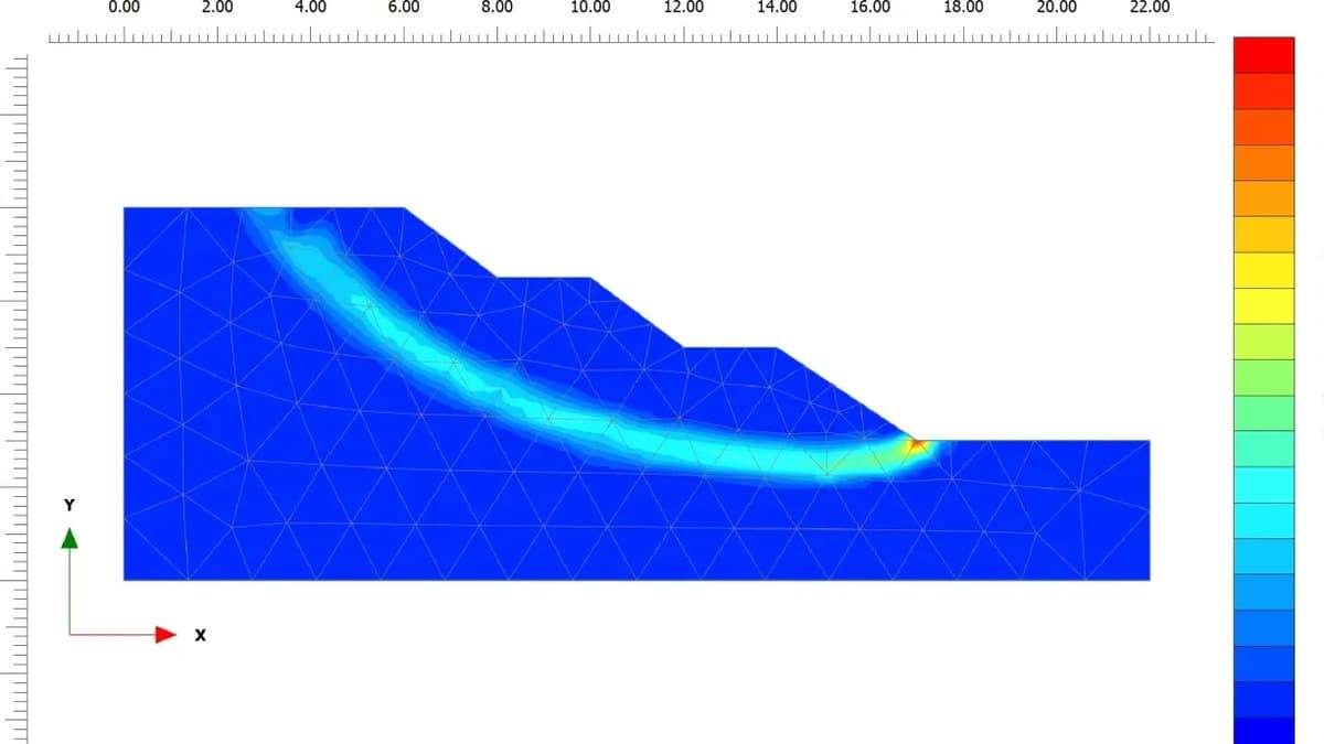
- Plastic points and mobilised shear. Where yielding has spread, and how close the ground is to forming a mechanism at working load.
- Excess pore pressures. The state of consolidation, drainage times, and where undrained behaviour still governs.
- Factor of safety by strength reduction. The software reduces c and tan φ until failure occurs, so the critical mechanism emerges from the analysis instead of being assumed in advance.
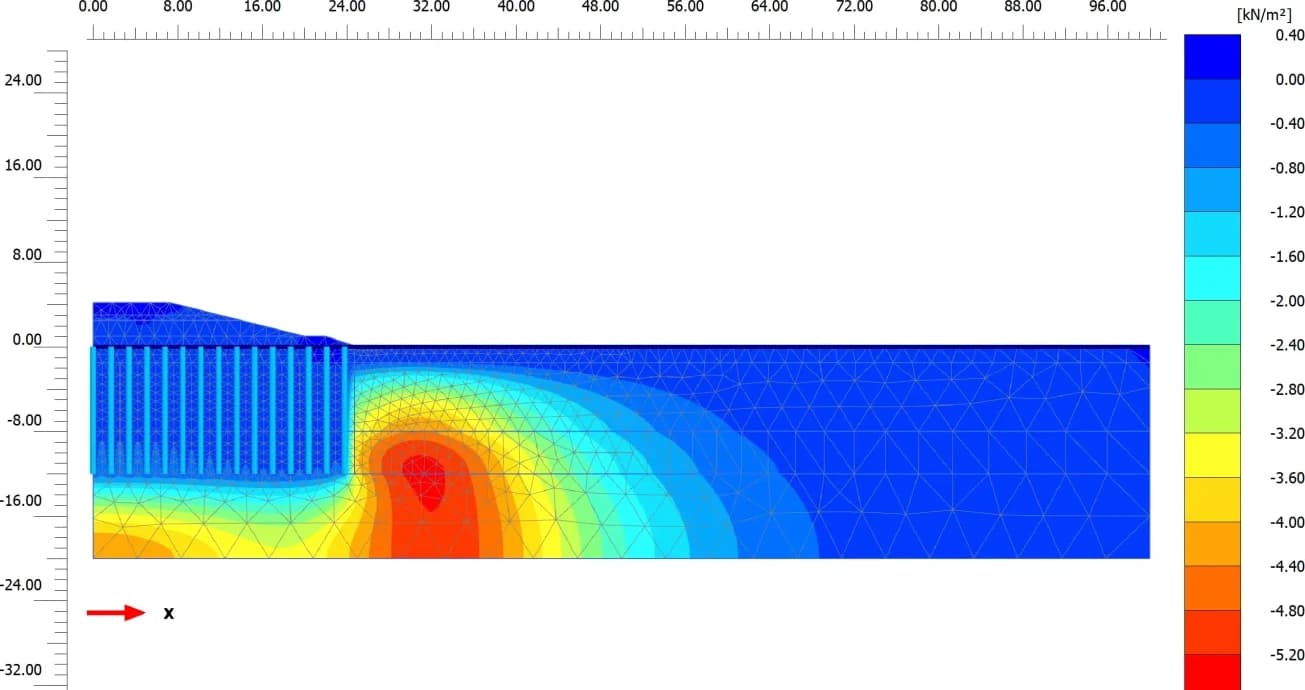
None of this replaces engineering judgement; it concentrates it. The engineer still chooses the constitutive model, the parameters and the stages, and the analysis magnifies the quality of those choices. Good soil data behind a fitting model produces predictions worth building on. Poor data produces contour plots with no authority behind them.
The tool for this

Finite-element analysis for soil and rock.
Model deep excavations, slopes, tunnels and foundations in 2D and 3D, with staged construction, consolidation and dynamic analysis.
FAQs
What is finite element analysis in geotechnical engineering?
A numerical method that divides the ground and its structures into a mesh of elements, assigns each a soil or rock material model, and solves for displacements and stresses under the applied loads and construction stages. It predicts deformation and stability together, where classical methods handle only one at a time.
Why do geotechnical problems need FEA when hand calculations exist?
Hand methods assume idealised geometry, homogeneous ground and single-stage loading. Real problems combine layered soils, nonlinear stiffness, staged construction and groundwater flow, and FEA carries all of these in one model. Hand calculations remain valuable for preliminary sizing and as an order-of-magnitude check on the model's output.
How does FE slope stability differ from limit equilibrium?
Limit equilibrium assumes a slip surface and checks equilibrium along it. Strength reduction FEA weakens the soil progressively, reducing c′ and tan φ′ until a mechanism forms on its own, so the factor of safety comes with the critical failure surface found rather than assumed. The two agree well on regular slopes; FE earns its keep where the mechanism is not obvious, such as reinforced slopes, seepage-driven cases or strongly layered ground.
When is a 3D model needed instead of 2D?
When geometry or loading varies in the third direction: tunnel headings, excavation corners, pile groups under general loading, or structures of finite length on a slope. Plane-strain 2D remains correct for long uniform cross-sections such as embankments and retaining walls, and it runs fast enough to explore parameters before committing to a 3D build.