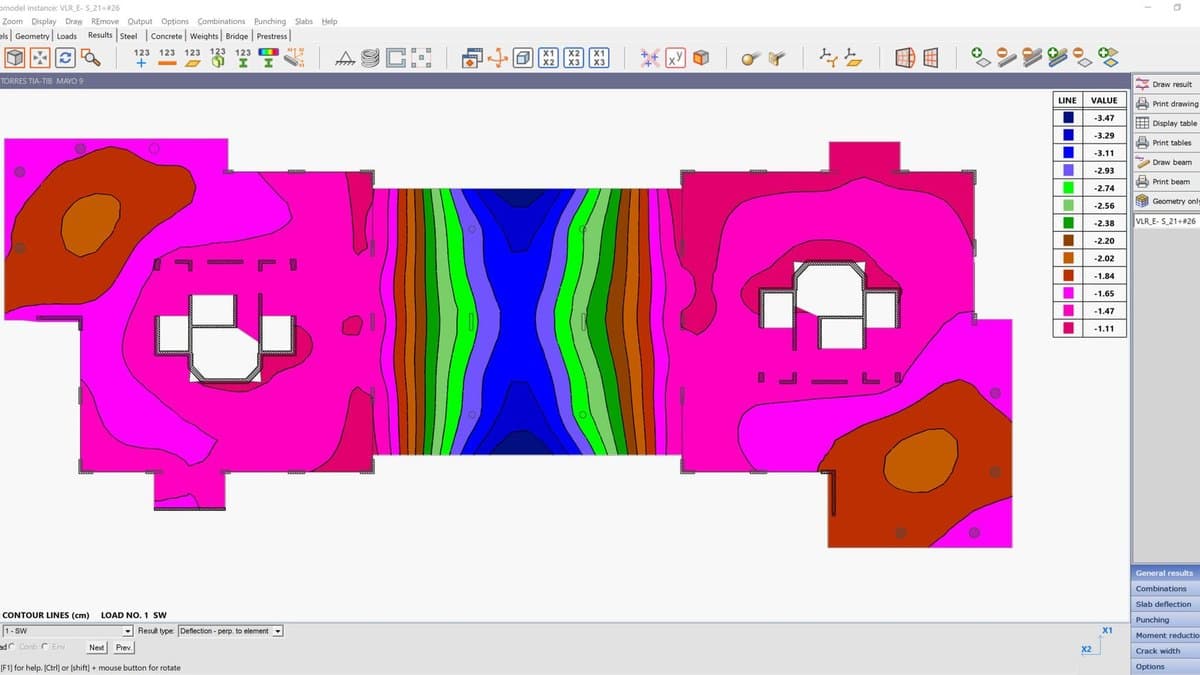





A shear wall is the spine of a building's lateral system. Wind and earthquake forces collected by the floor diaphragms feed into the walls, travel down through their in-plane stiffness, and arrive at the foundation as shear, overturning moment and uplift. Get the walls right and the rest of the frame largely follows.
Design practice is built on the assumption that a wall is a flat rectangle. But cores wrap around circular stair and lift shafts, tanks and silos are curved by function, and architects bend plan geometry for their own reasons. The moment a wall curves in plan it stops being a planar element and starts behaving as a shell, and the hand methods engineers lean on for straight walls stop applying.
This article covers what curvature actually changes, why the standard idealisations break down, how a finite element shell model produces forces a code check can accept, and what all of it means for the reinforcement on the drawings.
Why buildings need shear walls
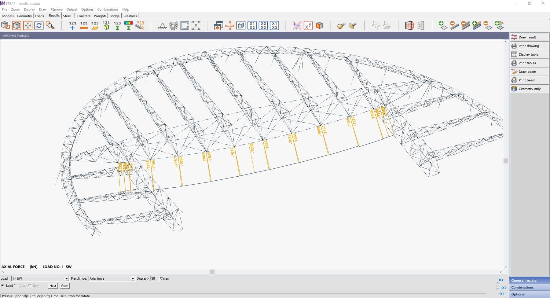
- They collect the lateral load. Floor diaphragms deliver wind and seismic forces to the stiffest vertical elements. A wall's in-plane stiffness is orders of magnitude greater than a column's, so the walls attract the load whether the designer intends it or not.
- They control drift. Storey drift limits, not strength, often size the wall. Stiff walls keep partitions, cladding and lifts within their movement tolerances.
- They resist torsion. Walls placed away from the centre of rigidity, and especially closed or near-closed core arrangements, give the building its torsional stiffness.
- They anchor the overturning. At the base the wall delivers concentrated shear and moment, and under seismic reversal the tension edge can see net uplift. Foundation design starts from these wall reactions.
What changes when the wall curves
A straight wall loaded in its plane carries membrane forces only: axial, in-plane shear and in-plane bending, all acting within the wall's own surface. A curved wall under the same lateral load cannot do that. Forces following the arc generate radial components, and the wall develops out-of-plane bending and transverse shear alongside its membrane action. The two behaviours couple: the wall is a shell, and each point in it carries up to eight stress resultants — three membrane forces, three bending and twisting moments, and two transverse shears.
Curvature is not all penalty. A closed or near-closed curved core acts as a tube, which is the most efficient torsion element a building can have. The price is paid in analysis and detailing rather than in material.
Openings raise the stakes further. A door or service opening interrupts the membrane force paths that carry the shear around the curve, concentrating stress at the corners and turning the strip of wall above the opening into a coupling element with its own design demands.
| Aspect | Straight wall | Curved wall |
|---|---|---|
| Load-carrying action | In-plane membrane forces only | Membrane and out-of-plane bending, coupled |
| Internal forces | Axial, shear, in-plane moment | Up to eight shell stress resultants at every point |
| Design section | Plane rectangular section | Curved section built by integrating the shell stress field |
| Hand idealisation | Cantilever and frame models work | No single bending plane; idealisations break down |
Why hand methods break down
The classical wall checks all assume a plane of bending. The cantilever idealisation treats the wall as a vertical beam with plane sections remaining plane. Squat-wall methods and strut-and-tie models assume the load path lives in one flat panel. A curved wall violates the premise: the neutral axis shifts with load direction, shear flows around the arc rather than across a section, and in-plane and out-of-plane actions cannot be separated and checked independently.
The tool that fits the problem is a finite element shell model. Shell elements represent the real curved geometry, real supports and real openings, and return the full set of membrane and bending resultants under every load combination. Mesh density matters: refinement around openings, at wall junctions and at the base is what captures the stress concentrations that end up governing the reinforcement.
From shell stresses to design forces
Shell stress resultants are not what code clauses are written for. Getting from the FE output to a code check takes one of two routes.
The first designs reinforcement directly from the shell resultants, treating the wall as layered membranes and proportioning each face's mesh for the combined membrane force and bending moment at every point. It is general, but it produces a reinforcement field rather than a checkable member.
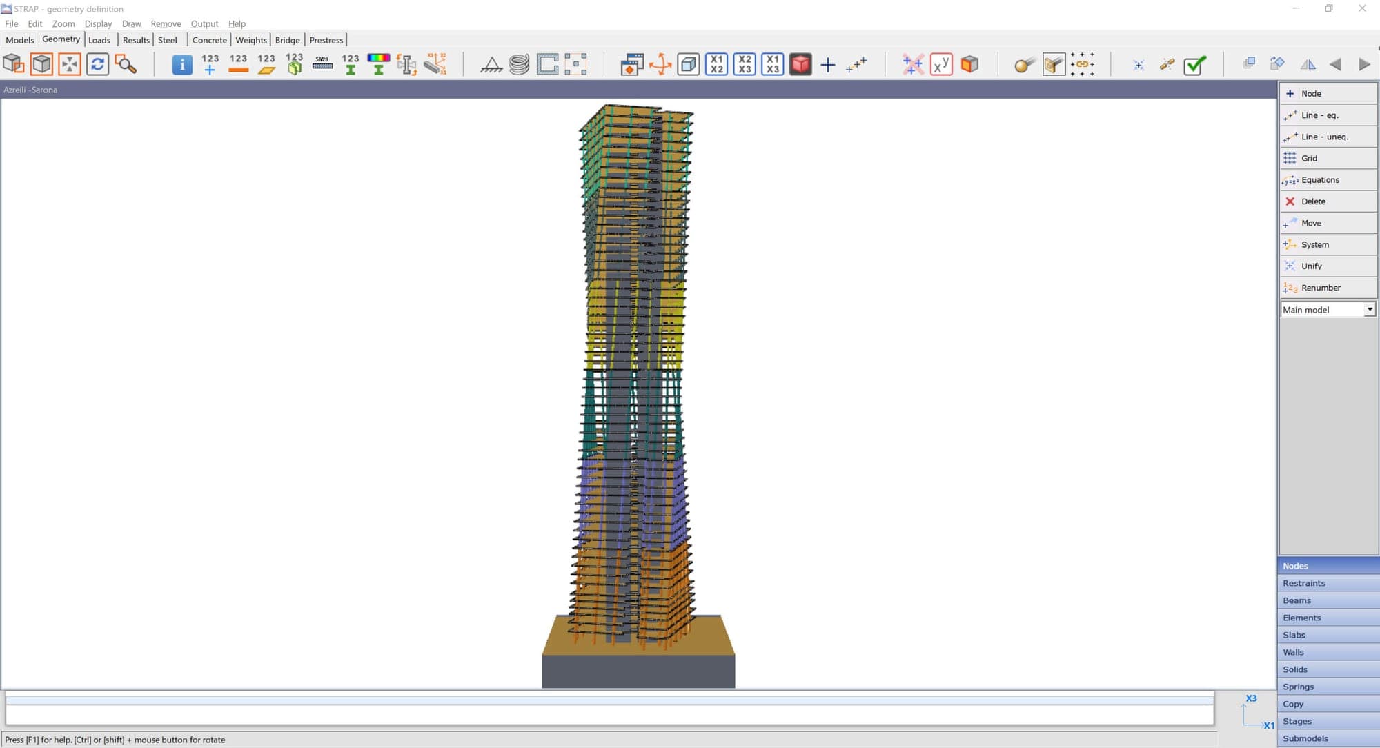
The second, and the one most projects use for primary walls, cuts the wall with integration strips, sometimes called design sections. A strip integrates the 2D stress components over a defined width and height of wall and condenses them into equivalent 1D member forces: axial force, biaxial moments, shear and torsion on the real curved cross-section. Those forces feed a conventional section check, with the actual rebar layout placed on the actual curved geometry, so every provision of the concrete code applies exactly as it would to a column or a beam.
The combinations matter as much as the sections. Internal forces from different load combinations do not peak at the same time, and serviceability combinations must be carried through separately so that crack-width and stress-limit checks run against the right force sets, not against ultimate values.
Reinforcement and detailing consequences
- Meshes follow the curve. Each face carries the usual two-way mesh, but horizontal bars are bent to the wall radius or delivered as short chords on large radii. The bending schedule has to state the radius explicitly.
- Through-thickness ties earn their place. Out-of-plane bending puts one face in tension and the other in compression. Links between the two meshes restrain the compression bars and carry the transverse shear the shell model reports.
- Boundary zones at ends and openings. Wall ends and opening edges collect the concentrated tension and compression from overturning. They get confined boundary detailing, and opening corners get trimming and diagonal bars against the stress concentrations the mesh revealed.
- Coupling elements above openings. The wall strip over a door works hard in shear. Detail it as a coupling beam with its own stirrups, not as leftover wall.
- Cover on curved formwork. Spacer layout and bar tolerances need attention where the formwork curves, or the cover the crack-width check assumed will not exist on site.
None of this is exotic anymore. Shell analysis, stress integration and curved-section checks are standard capabilities in structural analysis software, which moves the engineering judgement to where it belongs: choosing where to cut the design sections, which combinations govern, and detailing that makes the computed reinforcement buildable.
The tool for this

Structural analysis and design for every material.
Analyse and code-check steel, concrete and cold-formed structures — frames, slabs, shear walls and bridges — in one model.
FAQs
Why are some shear walls curved?
Circular stair and lift shafts, tanks and silos, and architectural plan geometry all produce curved walls. Curvature also has a structural upside: a closed or near-closed curved core behaves as a tube, giving the building far more torsional stiffness than the same area of straight walls arranged in a line.
Why can a curved shear wall not be designed like a straight one?
Straight-wall methods assume all forces act in one flat plane. Curvature couples in-plane membrane action with out-of-plane bending and transverse shear, so the wall carries up to eight stress resultants at every point and no single plane-section idealisation describes it. Only a shell model captures the coupled behaviour.
How are design forces obtained from a shell model of a curved wall?
Through integration strips, also called design sections. A strip integrates the 2D shell stresses over a defined width of wall into equivalent 1D forces, axial load, biaxial moments, shear and torsion, acting on the real curved cross-section. Those forces then go through a conventional code check with the actual reinforcement layout.
What extra reinforcement does a curved shear wall need?
The same two-way mesh on each face as a straight wall, plus what the coupled behaviour demands: through-thickness ties for out-of-plane bending and transverse shear, confined boundary zones at wall ends and opening edges, trimming and diagonal bars at opening corners, and horizontal bars bent to the wall radius on the bending schedule.