





Every simply supported steel beam sheds its load into the columns as a vertical reaction, and that reaction has to pass through the connection at each end. The action the connection carries is shear: a force acting across the beam's axis, trying to slice the web from the support.
Get the shear connection wrong and the beam is safe in bending but fails at its ends — the most common and least forgiving place for a steel frame to go wrong. This guide covers how shear force builds along a beam, how it loads the connection, the connection types that carry it, and how each is checked.
What shear force is, and where it peaks
Shear force, written V, is the internal force acting parallel to a beam's cross-section — perpendicular to its length. It comes from the applied loads: self-weight, imposed floor load, wind, or seismic action.
On a simply supported beam the shear is largest at the supports and zero at midspan. That is the opposite of bending moment, which peaks at midspan and vanishes at the ends. So the beam's ends — exactly where the connection lives — see the highest shear the member will ever carry.
- Read it off the shear force diagram. The diagram steps down by each point load and slopes under distributed load; its value at the support is the reaction the connection must transfer.
- The connection is sized for the reaction, not the moment. A simple (pinned) connection is designed to pass shear and to rotate freely, so it carries little or no moment by intent.
How shear loads the connection
The end reaction does not reach the bolts as a clean vertical force. It travels through the web, into the cleats or plate, through the bolt group, and into the support — and each step is a separate check.
- Bolts in shear. The bolt group resists the vertical reaction across the bolt shanks. A group offset from the support line also picks up a small moment, so the outermost bolts work hardest.
- Bearing and tear-out. The web and the connecting plate crush against the bolts and can tear toward a free edge; thin webs and short edge distances govern here, not the bolt.
- Block shear. A wedge of material can pull out of the beam web or the cleat along the bolt lines — a tension plane plus a shear plane failing together.
The connection types that carry shear

Three families cover most simple beam ends:
| Connection | How it carries shear | Where it suits |
|---|---|---|
| Double-angle (web cleat) | Two angles bolted to the web and the support | Beam-to-beam and beam-to-column, most common |
| Fin plate (shear tab) | A single plate welded to the support, bolted to the web | Fast erection, tolerant of fit-up |
| End plate (partial depth) | A plate welded to the beam web, bolted to the support | When a tidy, stiffer end is wanted |
Each is a simple connection: enough flexibility to let the beam end rotate, enough strength to pass the reaction. The choice is driven by fabrication, erection access, and how much rotation the design assumes.
Designing and checking a shear connection
A shear connection is verified against every load path in turn, and the lowest capacity governs:
- Bolt shear on the connecting bolts, single or double shear as detailed.
- Bearing and tear-out in the web and in the cleat or fin plate.
- Block shear on the beam web and on the plate.
- The coped section, if the beam is notched to clear a flange — reduced shear area and web buckling.
- The weld to the support, where one is used.
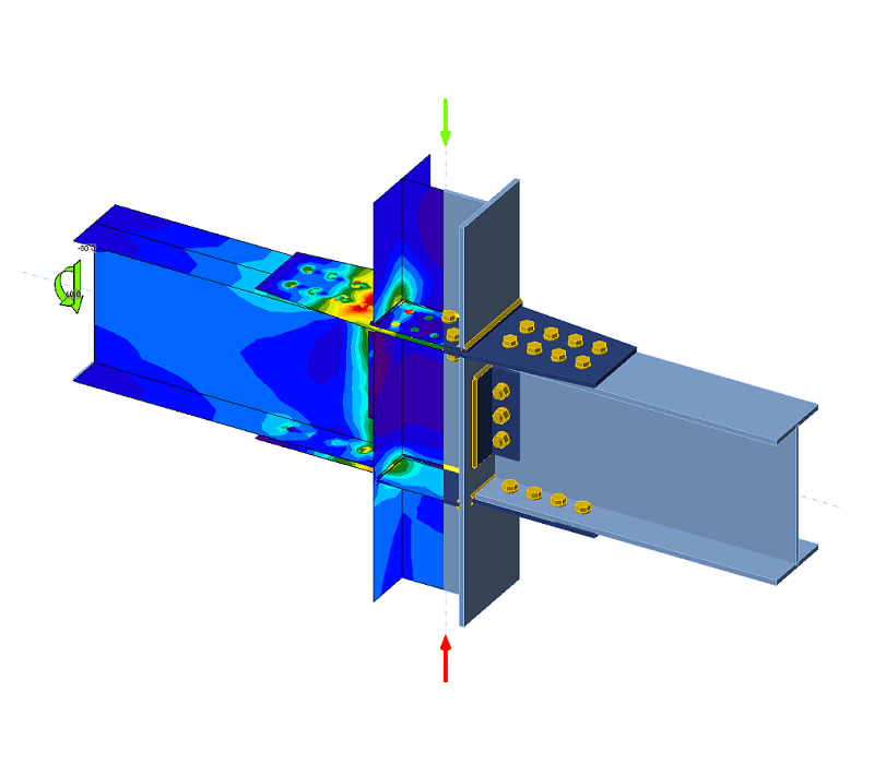
Doing this by hand for an irregular joint — a coped beam framing skew into a column web — is where errors creep in, because each check reads off a different area and the critical one is rarely obvious up front. Connection software on the real geometry runs every check at once and shows which one governs, so the weak link is explicit rather than assumed.

The tool for this

Code-check any steel connection to AISC & Eurocode.
Model welded, bolted and moment connections on the real geometry with CBFEM — clear pass/fail results and a full report in minutes.
FAQs
Where is shear force largest in a beam?
At the supports. On a simply supported beam the shear is maximum at each end and zero at midspan — the reverse of the bending moment, which peaks at midspan. That is why the connection at the beam end is the critical location for shear.
What is the difference between a shear connection and a moment connection?
A shear (simple) connection transfers the vertical reaction and is detailed to rotate freely, so it carries little moment. A moment connection is stiff enough to transfer bending as well, holding the beam and column at a fixed angle. The two are designed and checked differently.
Why can a shear connection fail even when the bolts are strong enough?
Because the bolt is only one of several load paths. Bearing on a thin web, block shear tearing a wedge out of the web or cleat, or a coped end buckling can all govern before the bolt shears. The connection is only as strong as its weakest check.
How is shear force in a steel connection checked?
Every path is verified: bolt shear, bearing and tear-out, block shear, the coped section, and the weld. The lowest capacity governs. Connection design software checks all of them on the actual geometry at once and reports which one is critical.


