





Every bolted steel connection resolves its forces into two actions at the bolt: shear, acting across the bolt's axis, and tension, pulling along it. A splice in a truss chord loads its bolts almost purely in shear. A hanger or an end-plate moment connection loads its bolts in tension. Most real joints do some of both.
The distinction matters because a bolt does not resist the two actions equally, the failure modes are different, and design codes check them with different formulas — plus an interaction check when they act together. This guide walks through how each mechanism works, which one governs, and what that means for connection design and detailing.

How a bolt carries shear
When two plates try to slide past each other, the bolt shank resists the sliding force across its cross-section.
- Single vs double shear. A lap joint cuts the bolt on one plane (single shear). A member sandwiched between two cover plates cuts it on two planes (double shear), roughly doubling the capacity of the same bolt.
- Bearing goes with it. The plate pushes on the bolt shank and the shank pushes back on the hole edge. Bearing capacity depends on plate thickness, steel grade, and the end and edge distances of the hole — not on the bolt alone.
- The shear plane matters. If the threaded portion of the bolt crosses the shear plane, the resisting area drops from the gross shank area to the smaller tensile stress area, cutting shear capacity by roughly a fifth. Codes provide separate values for "threads in the shear plane" and "threads excluded".
The governing failure is either the bolt shearing through, the plate crushing in bearing, or the plate tearing out toward a free edge — whichever is weakest.
How a bolt carries tension
A bolt in tension is loaded along its axis: the connected parts try to pull apart and the bolt holds them together.
- The threads set the capacity. Tension resistance is calculated on the tensile stress area at the threads, using the bolt's ultimate strength with a partial safety factor.
- Prying adds hidden force. In end-plate and T-stub connections, a flexible plate levers against its edges and increases the bolt tension beyond the applied load. Thicker plates and stiffeners reduce prying; codes make you account for it either way.
- Preload changes behaviour, not ultimate strength. A pretensioned bolt clamps the plates so the joint stays rigid and fatigue-resistant in service, but its ultimate tension check is the same as a snug-tight bolt.
So which is stronger — a bolt in shear or in tension?
Tension. For the same bolt, shear resistance is roughly 60% of tension resistance. That ratio comes from the mechanics of steel itself: yielding under pure shear occurs at about 1/√3 (≈ 0.58) of the tensile yield stress, and design codes carry a factor close to 0.6 into the bolt shear formulas.
Two caveats keep this from being a free win for tension-side design:
| Aspect | Bolt in shear | Bolt in tension |
|---|---|---|
| Resisting area | Shank (or thread) cross-section | Tensile stress area at threads |
| Typical capacity | ≈ 0.6 × tension capacity | Reference value |
| Extra effects | Bearing, tear-out, thread-plane position | Prying action, thread stripping |
| Usual governing side | Often the plate (bearing) | Often the bolt itself |
First, a shear connection often fails in the plate — bearing or tear-out — before the bolt shears, so the bolt ratio alone doesn't decide the joint. Second, tension bolts carry prying amplification that shear bolts don't. The honest engineering answer: the bolt is stronger in tension, but the connection is only as strong as its weakest check.
Shear and tension at the same time
Base plates under uplift with horizontal shear, bracing end connections, and moment end-plates all load their bolts in both directions at once. A bolt working near its full tension capacity has little shear capacity left, and vice versa.
Codes handle this with an interaction check — the utilisations in shear and in tension are combined (linearly or on a curve, depending on the code) and the sum must stay under 1.0. In practice this is where hand calculations get error-prone in irregular joints: each bolt row sees a different mix of forces, and the distribution shifts as plates yield.

Bearing-type vs slip-critical connections
There are two philosophies for shear transfer, and they change what the bolt actually does:
- Bearing-type connections let the plates slip a fraction of a millimetre until the shank bears on the hole. Cheaper to install; the checks are bolt shear plus plate bearing. This is the default for most static, non-reversing loads.
- Slip-critical (friction-grip) connections pretension high-strength bolts so the clamped plates transfer shear by friction — the bolt shank never bears at service loads. Required where slip would matter: fatigue-loaded joints, load reversal, oversized or slotted holes.
A slip-critical joint is still checked as a bearing joint at ultimate load, so the two philosophies converge at the strength limit state.
Detailing rules that protect both mechanisms
- Respect minimum pitch, end and edge distances — bearing and tear-out checks assume them.
- Keep bolt grades and diameters consistent within a joint; mixed stiffness concentrates force in the stiffest fastener.
- For tension groups, stiffen or thicken flexible end plates before adding bolts — prying grows faster than capacity.
- On drawings, state whether threads are excluded from the shear plane and whether pretension is required; both change site practice.
- In seismic or vibration-prone structures, specify locking or pretension so tension bolts cannot work loose.
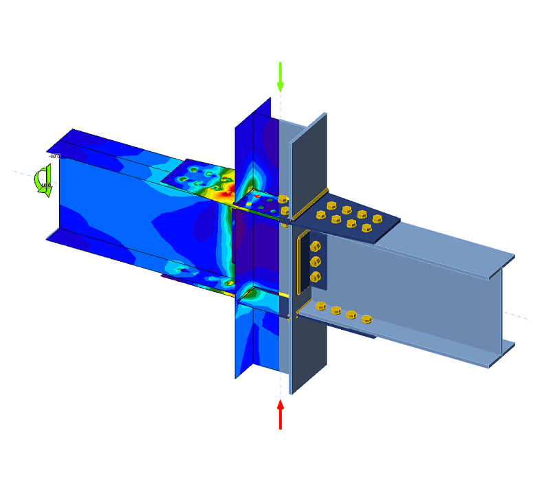
Checking all of this by hand is manageable for a standard joint and error-prone for a real one — multiple bolt rows, combined actions, prying, and plate checks interacting. This is exactly the class of problem component-based FEM connection software was built for: every bolt's shear, tension, bearing and interaction utilisation resolved together, on the actual geometry.
The tool for this

Code-check any steel connection to AISC & Eurocode.
Model welded, bolted and moment connections on the real geometry with CBFEM — clear pass/fail results and a full report in minutes.
FAQs
Are bolts stronger in shear or in tension?
In tension. A bolt's shear resistance is roughly 60% of its tension resistance, because steel yields in shear at about 58% of its tensile yield stress. The connection as a whole can still be governed by plate bearing, tear-out, or prying, so the bolt ratio alone never decides a design.
What is the difference between shear and tension in a bolt?
Shear loads the bolt across its axis — the connected plates try to slide and cut the bolt. Tension loads it along its axis — the parts try to pull apart and stretch the bolt. Shear capacity is set by the cross-section at the shear plane; tension capacity is set by the tensile stress area at the threads.
Can a bolt resist shear and tension at the same time?
Yes, but the two capacities are not independent. Design codes apply an interaction check that combines the shear and tension utilisations and limits their sum, so a bolt near its full tension capacity has little shear capacity left over.
Why does thread position change shear strength?
If threads cross the shear plane, the resisting area is the smaller tensile stress area instead of the full shank, reducing shear capacity by roughly 20%. Detailing bolt length so the shank sits at the interface avoids the penalty.
What is a slip-critical connection?
A shear connection whose pretensioned bolts clamp the plates hard enough to transfer load by friction, so no slip occurs at service loads. It is used where slip or fatigue would be damaging; at ultimate load it is still verified as a bearing-type connection.
Which failure modes should be checked in a bolted connection?
Bolt shear, plate bearing and tear-out, block shear of the connected part, bolt tension including prying, thread stripping, and combined shear–tension interaction. The governing mode is simply the weakest of these for the actual geometry.


