





Walk into almost any warehouse, factory or aircraft hangar and the structure overhead is the same one: two columns, two sloping rafters, and rigid connections at the knees and the apex. That is a steel portal frame, and it has been the default answer for single-storey industrial buildings for over half a century.
The reason is the load path. Because the knee joints are moment-resisting, the columns and rafters act as one bending system. Vertical load on the roof and wind on the walls are both carried by frame action, so no internal columns are needed and the whole floor plate stays clear. Spans of 20 to 40 m are routine; tapered-member frames go well beyond that.
The economy, though, is not automatic. It comes from a handful of specific decisions: where the haunch goes and how deep it is, whether members taper, how in-plane and out-of-plane stability are secured, and whether the frame is designed elastically or plastically. This post walks through each.

What a portal frame is, and why it dominates
A portal frame is a rigid plane frame: columns and rafters joined by moment connections at the eaves and apex, usually on pinned bases to keep the foundations small. Loads flow from cladding to purlins and side rails, into the rafters and columns, and down to the foundations through bending and axial force in the frame itself.
Three things make it the workhorse of single-storey construction:
- Repetition. One frame is designed once and repeated every bay, typically at 6 to 8 m centres. The engineering effort per square metre of building is very low.
- Clear span. Rigid knees shift moment from mid-span to the eaves, so the rafter works far harder than a set of pin-ended beams of the same depth would. The floor stays free of columns for racking, cranes and process layout.
- A light envelope. A shallow roof pitch, commonly around 6 degrees, with cold-formed purlins and metal sheeting keeps gravity load down, which feeds straight back into lighter frames.
Haunches and tapered members
Under gravity load the bending moment diagram of a portal is anything but uniform. It peaks sharply in hogging at the eaves, drops through the span, and rises again modestly at the apex. Sizing a constant rafter for the eaves peak wastes steel over most of its length.
The classical fix is the haunch: a local deepening of the rafter at the knee, often cut from the same rolled section, extending over roughly the first tenth of the span and about doubling the depth at the connection. The haunch does two jobs at once. It carries the hogging peak so the rafter proper can be one or two serial sizes lighter, and it deepens the bolted end-plate connection, increasing the lever arm and cutting the bolt and weld forces.
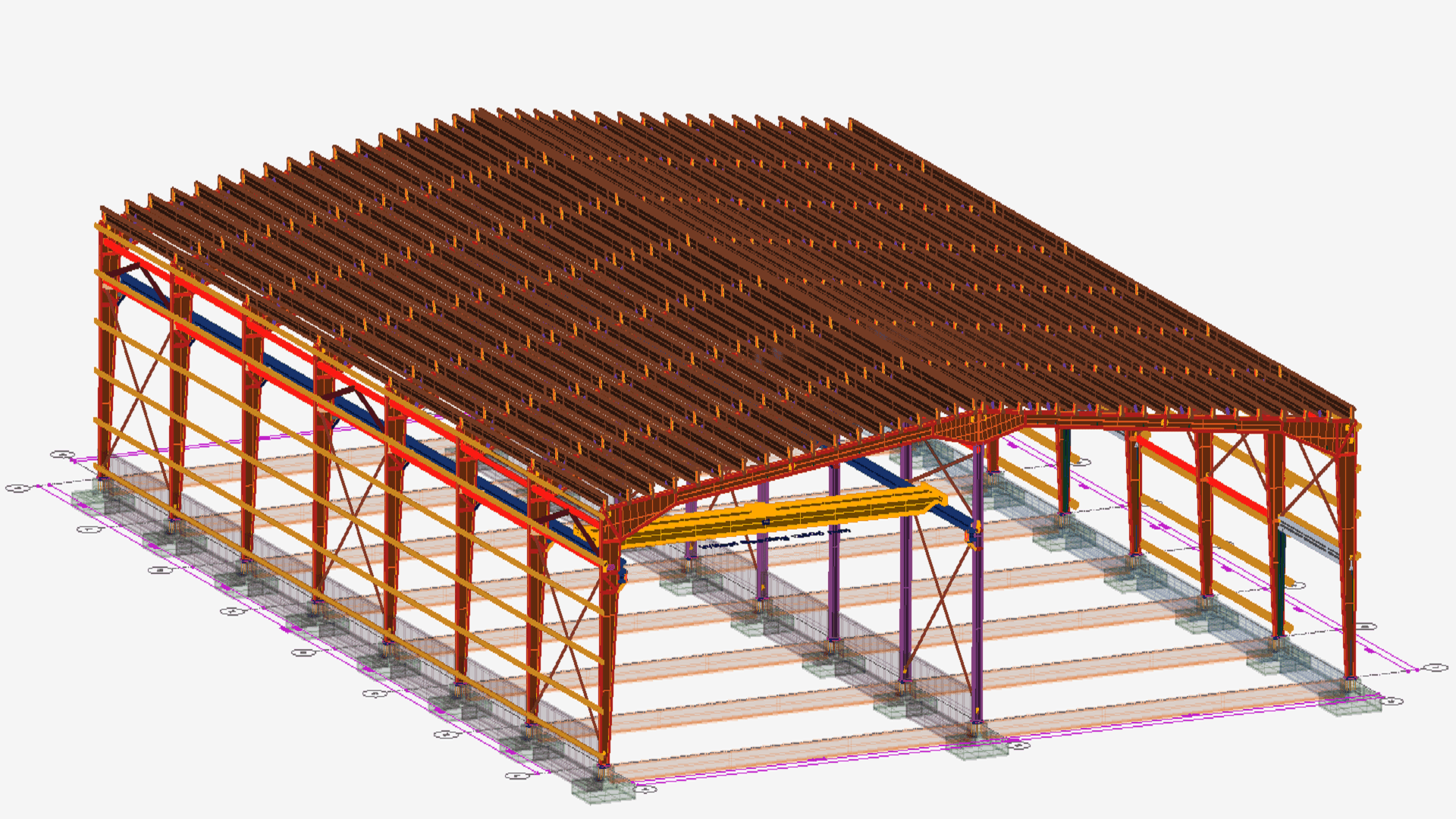
Pre-engineered building practice takes the same idea to its limit. Instead of a rolled section with a haunched end, columns and rafters are welded plate girders whose web depth tapers continuously, so the section profile tracks the moment diagram along the whole member. That is the core of the PEB proposition: put steel only where the demand is.
Stability is the real design problem
Strength rarely governs a well-proportioned portal. Stability does, in two distinct planes.
In-plane: sway and second-order effects
Pinned bases and slender columns make portals sway-sensitive. Horizontal deflection at the eaves under wind, and the amplification of moments as the frame leans under vertical load, both need checking. Codes require the designer to classify the frame's sway sensitivity from its elastic critical load and either amplify the first-order moments or run a second-order analysis. Eaves deflection limits also protect the cladding: sheeted walls tolerate movement of the order of height/150, while brittle cladding such as masonry demands much tighter limits.
Out-of-plane: the flange nobody restrained
Purlins and side rails restrain the outer flange of every member, because that is where they connect. Under gravity load, however, the compression at the haunch and eaves sits on the inner flange, which has no restraint at all. Left alone it fails by lateral-torsional buckling long before the section yields. The fix is fly braces, diagonal stays from a purlin or side rail down to the inner flange at defined positions through the haunch region. Under wind uplift the moment reverses and the mid-span inner flange of the rafter goes into compression instead, so the two load cases demand restraint in different places.
Elastic or plastic design
Portal frames can be designed by either method, and the choice shapes the whole frame.
| Aspect | Elastic design | Plastic design |
|---|---|---|
| Moments | Elastic peaks stand as calculated | Hinges form and moment redistributes into the span |
| Sections | Sized (or tapered) for the elastic peaks | Uniform sections work harder; Class 1 required at hinges |
| Restraint | Normal stability checks | Hinge positions need dedicated torsional restraint |
| Where it wins | Tapered PEB frames, crane buildings, complex geometry | Uniform rolled sections on standard spans |
Plastic design earns its keep on frames built from uniform rolled sections, where redistribution lets the mid-span section carry some of what the eaves cannot. Tapered PEB frames are analysed elastically, because the taper already matches capacity to the moment diagram and a continuously varying welded section is not a reliable place to demand hinge rotation. Both routes are legitimate; mixing their assumptions is not.
Bracing carries the third direction
Everything above happens in the plane of the frame. Wind on the gable walls, crane surge and erection loads act along the building, and the portal has almost no stiffness in that direction. A separate bracing system carries them: diagonal plan bracing in the roof of the end bays collects the longitudinal load, purlins and eaves struts feed it in from the intermediate frames, and vertical bracing in the side walls takes it down to the foundations. One braced bay can stabilise a long run of frames, provided the eaves members dragging force to it are designed for the job.

Where the optimisation actually happens
None of these decisions stands alone. Frame spacing trades against purlin spans. Haunch length trades against bolt count. Taper profile trades against the fly-brace layout the stability checks will demand. A competitive portal frame is the result of iterating that loop dozens of times across every frame in the building, which is precisely the work purpose-built PEB design software exists to do.
The tool for this

Design pre-engineered steel buildings in minutes.
Design portal frames, size members, detail connections and prepare estimates for PEB and single-storey steel structures — fast.
FAQs
What is a steel portal frame?
A single-storey rigid frame of columns and rafters connected by moment-resisting joints at the eaves and apex, usually on pinned bases. The rigid knees let the frame carry both vertical and horizontal loads by bending, so no internal columns are needed and the full floor area stays clear.
Why do portal frames have haunches?
The bending moment under gravity load peaks sharply at the eaves. A haunch deepens the rafter locally, typically over about the first tenth of the span, so that peak is carried without upsizing the whole rafter. It also deepens the bolted knee connection, increasing the lever arm and reducing the bolt forces.
What is the difference between elastic and plastic portal frame design?
Elastic design sizes the sections for the peak moments from an elastic analysis; plastic design allows hinges to form and redistributes moment into the span, which suits uniform rolled sections but requires Class 1 sections and dedicated restraint at the hinge positions. Tapered PEB frames are designed elastically, because the taper itself matches capacity to the moment diagram.
What clear spans can a steel portal frame achieve?
Spans of 20 to 40 m are routine and economical, and tapered-member frames extend well beyond that. Larger spans trade rafter weight against haunch size, deflection and out-of-plane restraint, which is why span, bay spacing and roof pitch are optimised together rather than fixed one at a time.


